Let's start with a sweet intro as the intro says everything about what we are doing here!
Introduction:
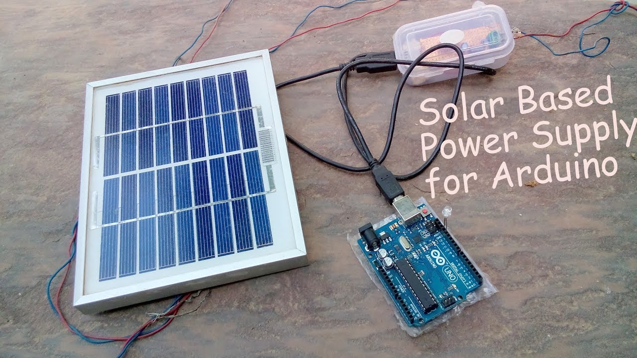
Solar is a Wide source of energy all around the Globe that is even used by aliens Who knows..:) We can make full use of it with many applications including electricity Generation, water heating, cooking food even lit a fire and the list is on and on. For electricity Generation, we are pretty familiar with Solar panels. They simply Convert light energy into electrical energy using photons present in energy packets of light energy Solar panels possess a simple physics but that is a subject for another tutorial. In this blog let's build something useful. So I decided to make utilization of this energy in order to charge my mobile or tablet. Also, it can be used to run other DC appliances(Low voltage and current) Like LED, Decoration lights, Power your Arduino even, etc.
So now in this, i will show you how to make DIY-Solar Energy USB Phone/Tablet Charger in a super easy way with a short tutorial
Let's Get Started!!
Let's Get Started!!
Step -1: Components you need
Here is the list of components we require:
1. 12v solar panel
1. 12v solar panel
2. Zero PCB or similar
3. PCB terminals
4. USB slot (you can salvage also)
5. Capacitors-10microF*2
6. 7805 Voltage Regulator
> Dc-Dc buck Converter will work fine
> Dc-Dc buck Converter will work fine
Tools you will need also:
- Soldering Iron
- Cutting/stripping tools
- Glue gun
Step -2: Little work on Solar Panel
When we buy a Solar panel, at the back side of it we will find two terminals that are one positive and the second negative. We will be going to add a terminal at the back side of the panel.
Just solder a diode at the positive terminal at the panel and then to the PCB terminal. Also, connect the negative of the panel to the second PCB terminal pin.
We now just need to insert the wires and tighten the screw.
Step -3: Preparing Circuit Module
It uses a very common and simple circuit in order to step down the solar panel to around 5.0v. This voltage is necessary to charge up the phone or any gadget which requires 5v.
If you want to know more about voltage regulator IC then refer to this link
Connect the circuit according to the schematic shown:


Step -4: Preparing the case for mounting the USB slot and circuit


I use simple plastic casing laying around in my garage. You can salvage from any old packaging.
Just trim off a slot equal to USB and also two holes opposite to the USB slot for the input terminal from the Solar panel.
If necessary file it. Insert the USB into place as shown in the photos
Step -5: Soldering time!


Solder the wire to the USB pins that is the outer pins of the slot. Middle pins are for the Data connections we need not required to connect anything with them. So leave them.
Solder the Circuit as per the schematic. Connect the USB to the Circuit as shown. Now we are ready to install them into the case.
Step -6: Assembling everything and Packing
Insert the USB into the case properly and glue it.
Trim off the unnecessary PCB such that it can Fit into our Plastic Case. If needed to Add support to USB with the help of a piece of paper as I did in the pictures.
That Green terminal is used to connect to Solar Panel. Glue them all and finally, we are done.
Connect the wires as long as you want as per your requirement.
Plug the USB cable into the slot
Connect to your phone or tablet.
Step -7: See what you have made!!

Finally, We have made our simple and Cheap Solar USB charger. It can charge your mobile for free, and credit goes to Sun.:) Yeah!
Hope you liked this blog.
Please share if you think it was awesome and see the videos for working on such a project and first charging.
Don't forget to follow for more cool projects!!
Feel free to have any queries.
More videos on my Youtube channel
Feel free to have any queries.
More videos on my Youtube channel
#Thanks.


